Temperature Controller
Description
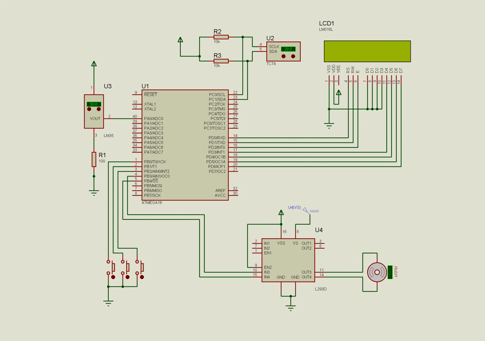
This project works as a temperature controller (proof of concept). An ATmega16 microcontroller reads the temperature from two sensors and regulates the speed of a fan accordingly.
Work objective. Increase the knowledge of programming of serial interfaces on the ATmega16 microcontroller in the field of embedded systems.
Parts used
- ATmega16
- TC74 temperature sensor (TWI)
- LM35 temperature sensor (analog)
- Push buttons
- LCD screen
- DC motor
- L293D motor driver
Tasks
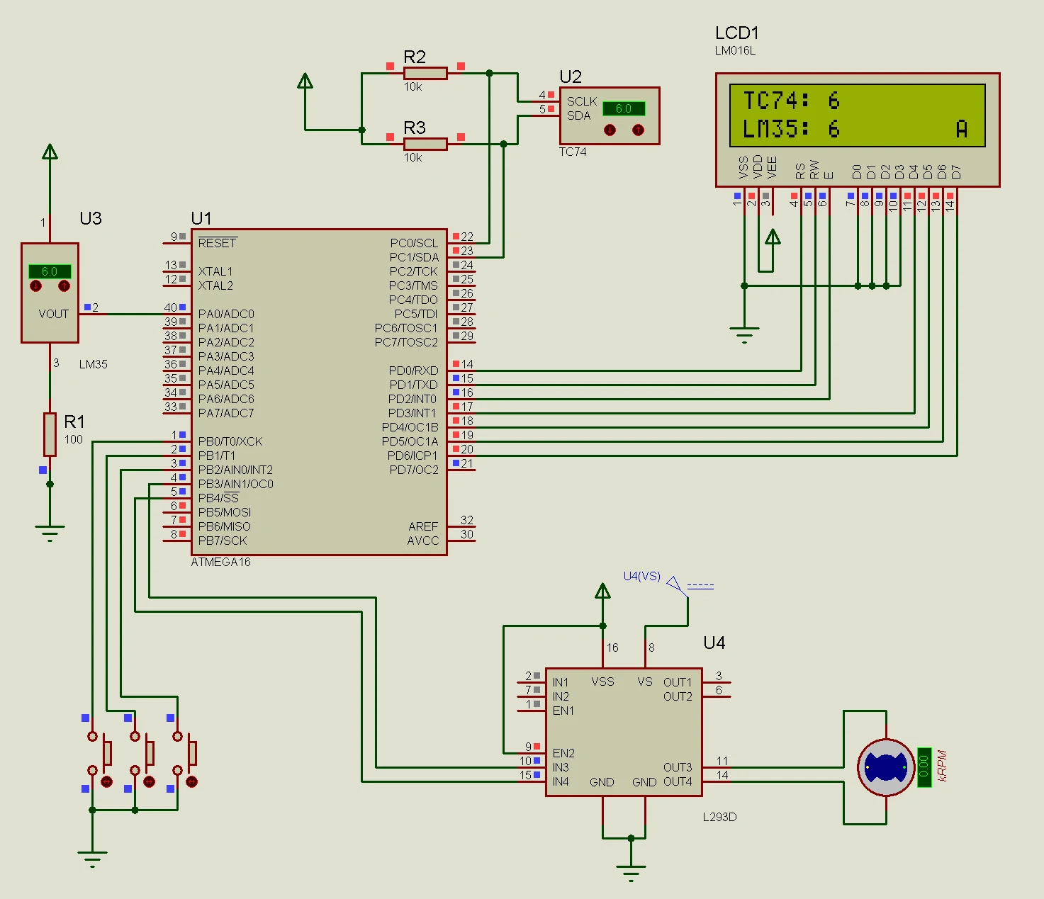
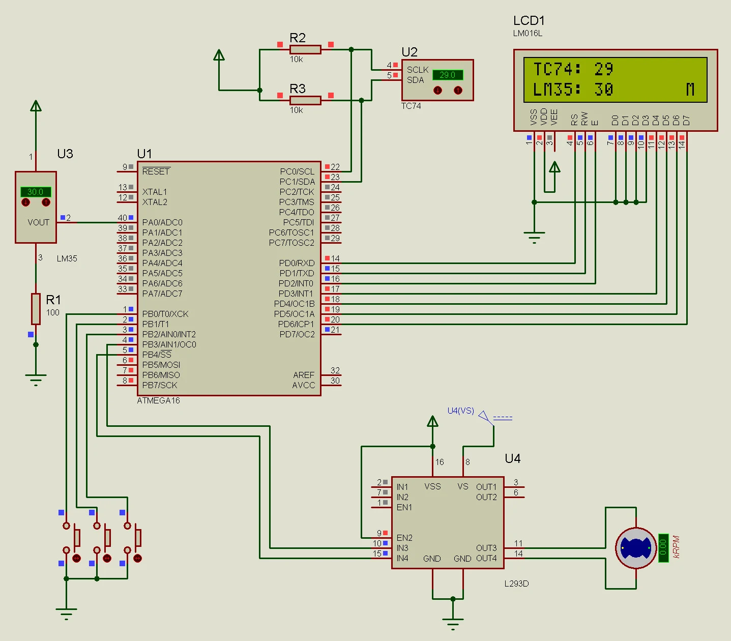
- The temperature, which was recorded with the TC74 digital temperature sensor, should be transmitted to the microcontroller through the TWI serial interface and displayed on the LCD screen in the first line.
- The temperature, which was recorded with the LM35 analog temperature sensor, should be transmitted to the microcontroller and displayed on the LCD screen in the second line.
- It must be possible to control the speed of the DC fan motor in manual mode with two buttons. You can choose the step between different speeds independently. The fan motor should work at least in three different speeds.
- The DC fan motor should also have an automatic control mode. Button No. 3 should allow changing the DC fan motor control mode: manual or automatic. The selected control mode should be displayed on the LCD screen (the LCD screen may contain just the first letter: M for manual, A for automatic).
- The DC fan motor has to work in two different speeds in automatic mode depending on the temperature of the TC74 sensor: 0–10 °C the motor does not rotate; 11–20 °C the first speed; > 20 °C the second speed.
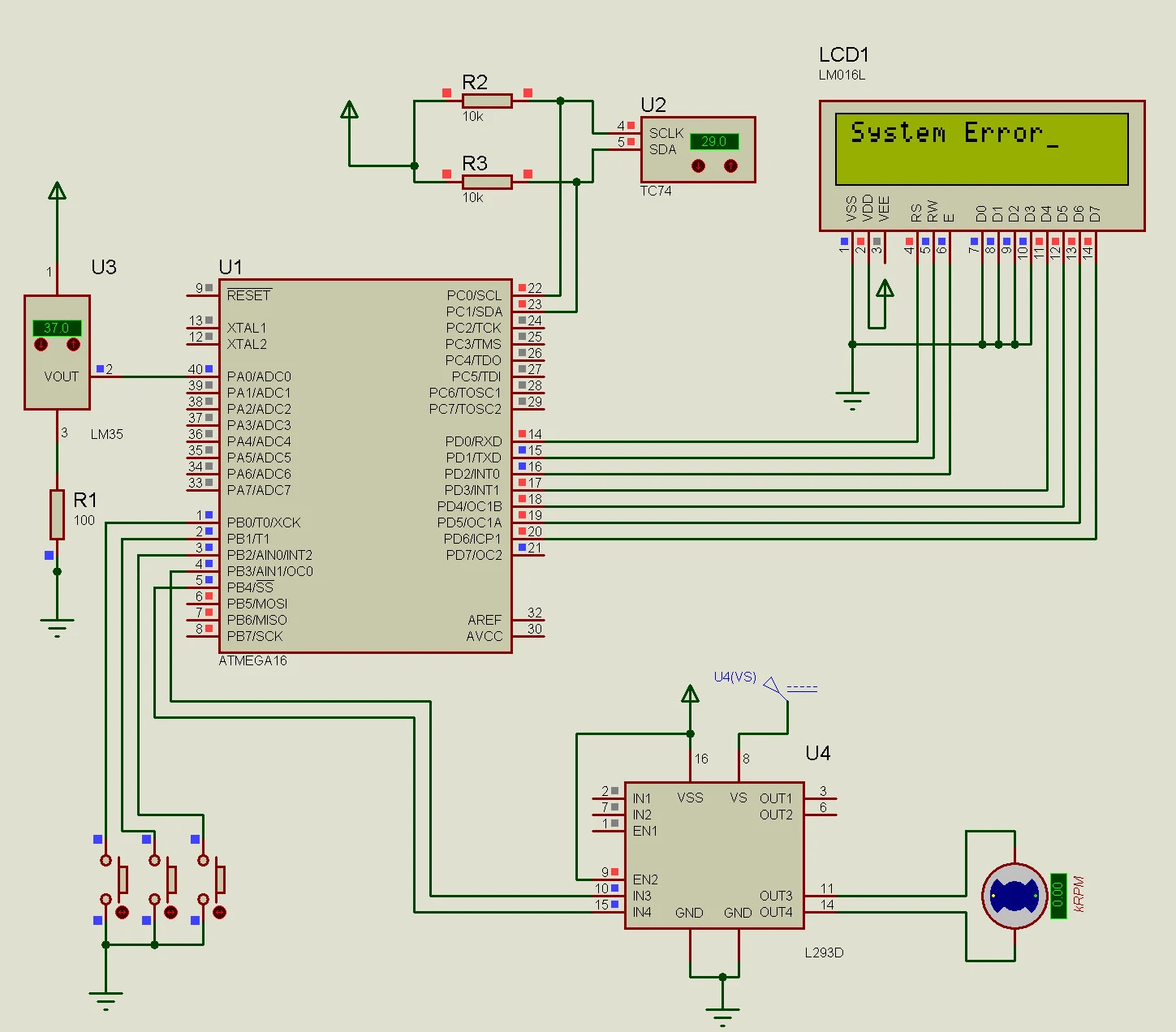
- Temperatures of the LM35 and TC74 sensors should be compared all the time. When the temperatures from both sensors vary by more than 5 °C, the "System Error" message should be displayed on the LCD screen. When the difference is reduced to less than 5 °C, the LCD should show the parameters from tasks 1–5 again.
Source and schematic
The source and the schematic are available on GitHub.